|
Dave's "Headlight Relay Upgrade Harness"
This list of instructions should help you in the making of the infamous "Headlight Relay Upgrade Harness" that a lot of people have ordered from Dave in Marysville Washington. Also known as (Zs-ondabrain) at classiczcars.com. I will attempt to make this process as painless as possible. Just follow along, step by step and be patient. It personally takes me a couple of hours to make the harness at home, between five kids and a long workweek. There is a lot of prep, which will actually help speed things up. Get as many, if not all the supplies in front of you before you start. Nothing is worse than starting, than having to stop again to go get a butt-connector or fuse holder. My camera sucks so the pictures are the best I could do. Here we go... |
||
|
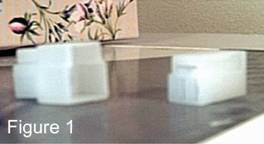
What's Needed (2) OEM style 3-pin male and (2) female plugs and their respective terminals. The hardest part for me to find was the white 3-pin connectors and the terminals that plug directly into my 35 year old Z-car. See figure 1.
I found my 240Z plugs at my local "Alternator and Starter" repair shop. He had to find them in one of his parts books. I had an idea to start there because while at the junkyard, I noticed a lot of newer Mazdas and Nissans were still using the same 35-year-old plug that I was in search of. Make sure that you order (4) female and (6) male brass terminals that work with that plug type. |
|
|
|
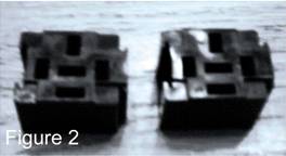
(2) After-market Automotive style relay sockets. See Fig. 2. I used a style that is very difficult to find, they were the best that I could find at the time. I used DEI (Directed Electronics Inc) relays and sockets. They came with almost every car-alarm that DEI makes (Python, Viper, Sidewinder) DEI now has built in relays in the alarms and they phased out the sockets. The nice thing about them was the fact that they had two sides, a male and a female which enabled them lock together. And there was no limit to how many you could attach together. I did however find a solid 2-relay socket from "The Right Connection" Look it up.
(2) Basic 30/40 after-market automotive grade relays (allows 30 amps to flow constantly with a 40amp surge) 4 or 5 pin (4-SPST 5- SPDT). You can find these at almost any auto parts store. They cost about $3.50 and up. If you look up and find "Micro" or TRC "The right Connection" online, they carry relays at a bulk and charge about $0.99 cents each. You might also find a good supplier by trying "12 volt supplier" in your search engine.
|
 |
|
|
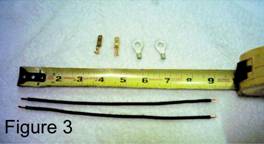
(23) Inches of 12 gauge stranded black wire. (This wire will be cut into 4 pieces, 2 @ 9" for the 2 ground wires that go from the headlight plug to the chassis, and 2 @ 2 1Ú2" for the power input from the fuse holder into the relay socket.
(2) 1/4" ring terminals with crimp type 10/12-gauge opening. See figure. 3 Zinc coated brass is the better 1 to choose. These two terminals will be used to bolt the headlight ground wire to the chassis. |
 |
|
|
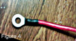
5/16" ring terminal with 10/12-gauge opening. See figure 4. This will be connected to the Battery so it's up to you whether you use zinc coated or solid brass terminals.
Multi-pack of black heat shrink. A multi-pack usually has 2 or 3 1/8" X 4" tubes, 2 or 3 1Ú4" X 4" tubes, and a couple 3/8" or 1Ú2" X 4" tubes. These will be needed for every area that you make a crimp on a terminal.
|
 |
|
|
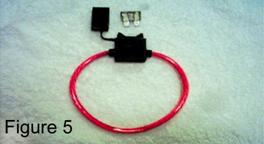
(1) Weather resistant fuse holder. See figure 5. Make sure you get the 10-gauge wire fuse holder and don't forget the 30 Amp fuse to go with that style fuse holder. A closable lid helps to keep it stealthy as well as watertight. The ones that I buy are usually uncut and in a ring shape. Cut the loop in the center, farthest away from the black holder. Opened up, it should be about 12" long from end to end.
|
 |
|
|
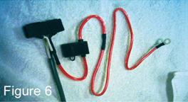
(1) 23" length of 10-gauge automotive power wire. See figure 6. DO NOT USE SOLID COPPER! Make sure it's stranded, the higher the strand count, the better and more flexible. Sleeve color doesn't matter because of the split loom you'll put on later.
|
 |
|
|
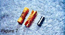
(4) Butt-connectors, 10/12 gauge (yellow) if you get insulated. Fig. 7 Non-insulated is available but Insulated are easier to find at the auto parts store. I strip the insulation off and use them that way.
|
 |
|
|
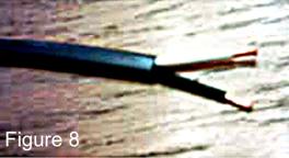
(53) inches of 12/2 RV wire. I only found this type of wire at the R.V. supply store. They use it for un-grounded power supply in the walls of Recreational Vehicles. See figure 8. It has a gray sleeve covering a black 12-gauge wire and a white 12-gauge wire. The wire is stranded copper.
(36) Inches of 1Ú4" automotive split-loom for covering the power wire.
(48) Inches of 1Ú2" automotive split-loom for covering the output wires.
|
 |
|
|
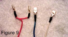
(3) Different colors of 16 or 18 gauge wire @ 29" long each. See figure 9. I use 1 red, 1 blue, and 1 white. These are the input wires that go from the stock harness plug to the relays. They power up the relays and turn on the low beams or high beams. I use red for power, white for low beam, and blue for the high beam.
|
 |
|
|
Start building here
|
 |
|
|
Headlight Ground Wires
1)
Cut 2 - 9"
lengths of the black 12-gauge wire from the 23" piece mentioned earlier. 2)
On each wire,
strip one side @ 1Ú4" for the 1Ú4" ring terminal, then strip the other end
@ 3/8" for the male (blade type terminal) that will go into the larger
of the 2 plugs (plugs into the headlight side) at a later time. 3)
Cut 4 pieces
of 1/8" heat shrink. 2 @ 1Ú2" for the ring side and 2 @ 5/8" for the male
terminal. 4)
Slide the
1Ú2" heat shrink onto the 1Ú4" stripped side of the wire then crimp the
ring terminal on, slide the heat shrink over the crimp to cover the
exposed wire, then shrink it with a heat gun or torch (be careful!) 5) Slide the 5/8" heat shrink onto the 3/8" stripped side. Crimp the terminal onto the wire as shown below. Fold the arms of the terminal over the wire. This is the best and only method that should be used when crimping ALL harness wires. Slide the heat shrink over when you're happy with the crimp you've made. Do not slide on farther than shown below. The terminal will not go into the plug properly if the heat shrink is on to far, (or to thick). Heat the heat shrink and set the completed wire assembly aside for later (one of the last steps of the harness assembly) Remember these few crimping and heat shrinking techniques.
|
 |
|
 |
||
 |
||
|
Fuse Holder Prep
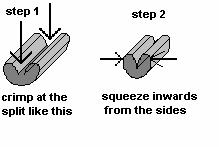
Cut the power wire at the center most point away from the black fuse holder as shown in the picture below. Strip both ends @ 1Ú4". Slide one of the non-insulated butt-connectors Fig. 7 onto one of the ends and crimp it partially to hold it in place.
|
 |
|
|
1) Slide a piece of 11Ú4 long 1Ú4" -heat shrink onto the 23" long 10 gauge power wire. Strip one end of the power wire @ 1Ú4". Attach it to the inline fuse holder using the pre-mentioned butt connector. Crimp both ends of the butt connector as tight as possible so there's no chance of the wires pulling apart. Then squeeze inwards to completely squeeze the wire. See above picture. Slide the heat shrink over the crimped butt connector and heat to shrink.
2) Cut the remaining 5" black 12 gauge wire, left over from making the grounding wire, into 2 pieces (2 1Ú2" each)
|
 |
|
|
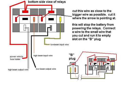
Relay Diagram
|
||
|
Overall Diagram
|
||