Headlight Relay Conversion For The Datsun 240-Z

by: Stephen Judkins
as of: 11 April 2001
Background:
My headlights are of marginal value. I was almost afraid to drive the Z at
night. I looked at a very good web page for doing a conversion to relays
by Daniel Stern Lighting, but I was
afraid to do it because I saw a
posting on the 240Z list that said the Z was wired differently. Fortunately
I decided to take a second look and see if I couldn't determine a way to
wire the relays.
The key to wiring the relays is to realize how the circuit is controlled. The circuit in the Stern Lighting page shows the headlight on/off switch wired to the dimmer switch, which then is wired to the high and low beams. I studied the wiring diagram in the 240-Z factory service manual. From this I realized the headlight switch is wired to the headlights, and the headlights are wired to the dimmer switch. I checked the voltages on a headlight which confirmed my studies of the wiring diagram. By the way, I was getting about 9.5 volts at the headlights.
Next I thought about where to put the relays. I was contemplating putting the relays under the dash for the cleanest install. However, nothing in my engine compartment looks that neat, so I went ahead with installing the relays there. Besides, there was a lot less wire to run.
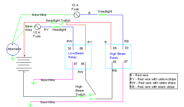
Here is an approximation of the current headlight circuit.
From the positive terminal, the wire goes to the headlight switch. A red wire goes
to the fuse box where it splits into a red wire (right headlight) and
red/yellow wire (left headlight). Those wires go to their respective
headlights. Each headlight has a red/white and red/black wire. The
red/white wire goes to the low beam side of the dimmer switch and the
red/black wire goes to the high beam side. From the dimmer switch a wire
goes to ground.
Purchase list:
10 butt splices
4 solderless lugs
14 Gauge wire
2 inline fuse holders
Dymo label maker and heavy duty paper labels.
From Radioshack (online or phone order):
2 relays, Cat.#: 900-2394, $2.99 ea.
2 relay socket wire harnesses, Cat.#: 900-2396, $2.59 ea
Project box to hold relays approximately $4
How to do it:
Prepare the project box by drilling 8 holes the same diameter as the wires
on the relay sock wire harnesses. Run the wires from 30, 85 and 86 for the
low beam and high beams out of the box. Label them 30 Low, 85 Low, 86 Low,
30 High, 85 High and 86 High. The wire for 87A will not be used. Leave the
wire for 87 in the box. If you are unsure which label to put on which wire,
compare with the relay for terminal numbers.
DISCONNECT THE BATTERY!!!!!!! TAKE OFF ALL JEWELRY!!!!!!
I attacked the wiring harness near the alternator. Years ago I had an electrical fire that required the replacement of a 3 foot section of the wiring harness. One of the places where I patched the harness was near the alternator. The wires were already cut there, so all I had to do was break my splices.
Anyway, open the wire loom and find the 12 gauge red wire (There is a 16 gauge red wire in the harness here.), the red/yellow wire, the red/white wire and the red/black wire. Place the following labels approximately 1.5 inches apart.
Label the wires as follows:
Color   Back (firewall)  Front (radiator)
R       86 High          Right fuse
RY      86 Low           Left fuse
RW      85 Low           30 Low
RB      85 High          30 High
Cut the wires in between the labels and strip the ends. Splice the inline fuse holders to the R and RY wires and attach lugs to the other end of the holders. Put the lugs on the positive terminal of the alternator. Splice the wires from the harness to the relays as they are labeled. Run two wires into the box and splice them to the 87 wires. Connect the other end of those wires to ground.
Look for any bare wire and cover/repair. Place 7.5 or 10 amp fuses in the fuse holders. Reconnect the battery and check your splices. Re-wrap the wiring harness and seal the project box.
NOTES:
1. As drawn, the headlight switch is off
2. As drawn, the low beam circuit relay is ready for power and would be on.
With the headlight switch off, neither relay receives power
3. The circles are fuses. 10A fuses were used, 7.5A would be the optimal size.