
Created : 980818
Last updated: 990326
This page is in general how I get to the ECU either to replace it, or to use it to run diagnostic tests on the car.
It's actually fairly easy to get to. First and MOST importantly, I always disconnect the car's battery if I am planning on removing/disconnecting the ECU from the car. Paranoid as I am, I tend to disconnect both terminals of the battery, although it's not really necessary.
In case you didn't know, the battery is under the hood on the right side of the car (as seen from the driver's perspective). (It's on the left and side for RHD (right hand drive) cars). The battery is on the same side as the passenger side (based on LHD versus RHD car).
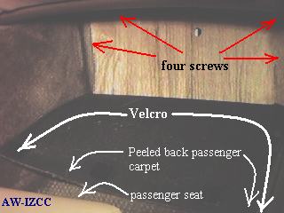
On the piece of wood, there are four screws (10 mm) holding it down.
Remove these four screws and then remove the piece of wood to expose the
area where the ECU lives.
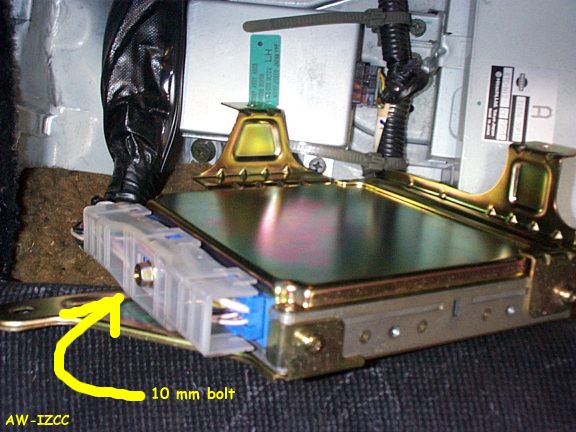
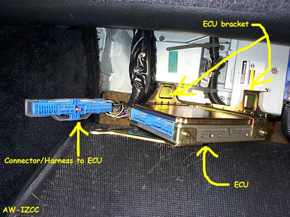
You can remove this wiring harness/connector by loosening the screwbolt
(10 mm) that is in the middle of the connector, this will allow you to
remove the connector from its connection to the ECU.
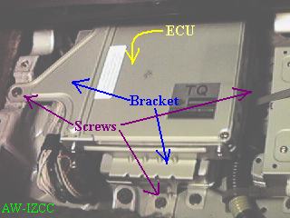
Once you have done this, you will notice that the ECU can now be easily
removed from the ECU bracket by 'twisting' the ECU and the bracket in different
directions. You do NOT have to bend any metal to do this.
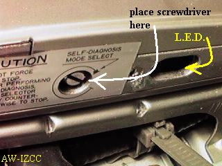
Get a flat head screwdriver so that it can fit into the slotted potentiometer,
which is located on the right hand side of the ECU. The oblong hold just
above the potentiometer houses an LED that will flash codes at you. This
flashing is mirrored by the 'engine' light on the dash.
To enter the diagnostic mode, turn the ignition switch to the 'on' position,
but do not start the car. Confirm that the LED is lit. The ECU is
now in what is called "mode I".
Read the resulting codes as it is being flashed via the LED, or the dash 'engine' light. It will flash the first digit with long flashes and then the second digit with short flashes. For example 4 long flashes followed by 3 short flashes means the number 43.
Note that more than one coding can be displayed, i.e. 11 may be displayed, followed by 21, in which case check the crank angle sensor first.
Here is a table of the codes with their meanings :
11: Crankshaft position sensor circuit
12: Mass air flow sensor circuit
13: Engine coolant temperature sensor circuit
14: Vehicle speed sensor circuit
21: Ignition signal circuit
31: ECM/ECU
*32: EGR function
33: Heated oxygen sensor circuit (Left side)
34: Knock sensor circuit
*35: EGR temperature sensor circuit
42: Fuel temperature sensor circuit
43: Throttle position sensor circuit
*45: Injector leak
*51: Injector circuit
53: Heated osygen sensor circuit (Right side)
54: Signal circuit from A/T control unit to ECM/ECU (A/T only)
55: No malfunctions in the above circuits
* : Not available for non-california models.
A little more meaning :
11 - crank angle sensor circuit, 1 deg or 120 deg signal is not received
for the first few seconds during engine cranking or not often enough at
high RPM- check harness, connectors and the crank angle sensor.
12 - Air flow meter circuit, open or short circuit is detected- check
harness, connectors and the air flow meter.
13- engine temperature circuit, open or short circuit is detected-
check harness, connectors and sensor.
21 - ignition signal circuit, the ECU is not detecting ignition signal
from the transistor ignition unit- check harness, connectors and power
transistor unit.
33- Oxygen sensor, - check harness, connectors and sensor.
34 - detonation sensor circuit , open or short circuit is detected-
check harness, connectors and sensor.
42 - Fuel temperature sensor circuit, open or short circuit is detected-
check harness, connectors and sensor.
43 - throttle sensor circuit, open or short circuit is detected- check
harness, connectors and sensor.
54 - signal circuit from the auto transmission computer is open or
short circuit check harness & connector. (Auto only)
When a particular fault is detected, it's held in memory for 50 engine starts, then deleted. If the fault disappears, then reappears, the count to 50 starts again. If at this point you want to retain the diagnostic result in memory, turn the ignition off, and wait 5 seconds for the ECU power supply relay to drop out. The ECU will drop out of mode II, and next time its turned on, it will start up in mode I. If you disconnect the battery for more than 24 hours, the fault codes will be lost in the ECU's back up memory.