
 Do you want electronic ignition on your 240Z? Don't want to pay through the nose?
Check this out!
Do you want electronic ignition on your 240Z? Don't want to pay through the nose?
Check this out!
The Following write-up was contributed
by: Kyle Hagemann IZCC #968.
You may visit Kyle's Personal Web Site at: http://www.sonic.net/~kyle" for additional information, or e-mail him directly at: kyle@sonic.net
(Last Up-dated 18 Mar. 2001)
This is very easy to do, and total cost is less than most aftermarket
setups. Here's what I spent, roughly:
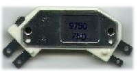
| Standard GM four-pin HEI module, like the one above |
|
| MSD Blaster II coil (optional) |
|
| Spade lugs for electrical connections |
|
| '76-78 distributor from a 280Z with mounting bracket (important) |
|
| New cap and rotor |
|
| Total cost |
$100.00 |
If you think this is something you're interested in, here's the details.
Here's the source for this article
- Grab a brew (but just one, mind you).
- Take the new distributor cap, and hook the spark plug wires up to it
in the right order.
- Unplug the black wire from the distributor, and remove the adjusting
screw.
- Slide the distributor out, noting the direction the rotor points.
- Remove the mounting bracket. This is the
part that the adjusting screw screwed into. It's held in with two
10 mm head bolts. This must be replaced with the proper mount for
the 280's distributor. If you screwed up and didn't get the mount
from the junkyard, you may be able to modify the stock mount and/or
the new distributor a bit to work.
 Check the new
distributor for proper operation. The vacuum and/or mechanical advance
may not work smoothly, so some detail work may be needed. Use your
judgment. Install the new rotor. I've heard a rumor that the
distributors from automatic-equipped cars have an electrical relay that
retards the timing. Hmmm. That could be hooked up to a knock
sensor or a switch inside the car. I'm going to see what I can figure
out about this, eventually....
Check the new
distributor for proper operation. The vacuum and/or mechanical advance
may not work smoothly, so some detail work may be needed. Use your
judgment. Install the new rotor. I've heard a rumor that the
distributors from automatic-equipped cars have an electrical relay that
retards the timing. Hmmm. That could be hooked up to a knock
sensor or a switch inside the car. I'm going to see what I can figure
out about this, eventually....- Install the new mount onto the timing case cover, sealing it with some
gasket goop. Make sure that the hole for the adjusting screw is toward
the front.
- Install the distributor with the rotor pointing in the same direction
as the old points distributor. Snap the cap on, and call it good.
- Down half your brew, and start 'er up.
- After you realize that it won't start because you still have a bunch
of new parts left,
- Make a bracket to hold the module in a position of your choosing.
I used a piece of 1/16" aluminum, bolted to
the lower coil mounting bolt. Drill it as necessary to hold the mod
with two sheet metal screws.
- Here you need to make a choice - are you using an
MSD coil or not? I say MSD Blaster II, but any coil designed for
12V input will work. The important distinction is between a 12V in
and a coil designed to work with a resistor. If you take out the
ballast resistor, but use a coil meant to have one, you will cook
the coil in very short order.... It is possible to use the stock coil,
and I will include stock-type coil instructions in small
type.
- Install the new coil in the same location as stock. Hook everything
up. Some of these connections will be disconnected in a few steps,
but this makes it easy to keep from getting mixed up.
- Take out the ballast resistor. This will leave a green/white
wire and a long black/white wire hanging loose. If you're
keeping a stock-type coil, leave the black/white wire hooked up.
 Make a Y-jumper
from a piece of wire. It should have two male terminals and one female.
Connect the female terminal to termial B on the module. Connect one
of the male terminals to the long black/white wire and the other to the
green/white wire. Take another swig - you've made the first electrical
connection. Then again, it's the most difficult connection to make,
so take two swigs. Or, you cheapos can make
a Y-connector with two females and one male connection. The male
connection gets hooked to the green/white wire. Then hook one of
the females to the naked side of the ballast resistor and the other to
terminal B. Got it? That's the only difference between the
two setups....
Make a Y-jumper
from a piece of wire. It should have two male terminals and one female.
Connect the female terminal to termial B on the module. Connect one
of the male terminals to the long black/white wire and the other to the
green/white wire. Take another swig - you've made the first electrical
connection. Then again, it's the most difficult connection to make,
so take two swigs. Or, you cheapos can make
a Y-connector with two females and one male connection. The male
connection gets hooked to the green/white wire. Then hook one of
the females to the naked side of the ballast resistor and the other to
terminal B. Got it? That's the only difference between the
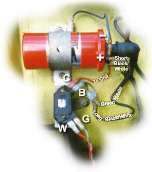
two setups....- There should be a black/white wire connected to the + side of the coil,
and another from that terminal to the noise-suppressing capacitor above
the coil. Leave them alone!
- There's a plain black wire connected to the - side of the coil.
Disconnect it, and make a jumper to connect terminal C on the module to
the - side of the coil.
- Attach a female connector to the + wire from the distributor (it should
be a red one). Connect it to terminal W on the module. By the way,
I've heard that some distributors have two green wires. To determine
polarity, Andy Levy says this can be done by rotating
the dist. shaft the same direction as it would be turned by the engine
and use a volt meter to establish the polarity. This system generates
AC current so look for a positive reading when the raised portion is
approaching the pick up and negative when it departs.
- The final connection is from the G terminal on the module to the negative
wire on the distributor. That should be a green one.
- Bolt your module mounting bracket to a convienient location and screw
the module into it. Be sure to use the included grease.
- Start it up, set the timing, and road test it.
- Everything satisfactory? Finish your adult beverage, likely very
warm and disgusting by now, and congratulate yourself on a job well done!
Another thing that might help is a good understanding
of how the stock system works in comparison to the HEI. If you prefer
simple how-to instructions, and don't really care why, skip this part.
Got your thinking cap on?
In the stock setup, you have a solid black wire that
runs from the coil - to the points. The points close as the dist.
turns, completing the circuit. On the + side of the coil, you have
a short black w/white wire. That wire is hooked up to two others
under the electrical tape. One is the longer black w/white wire connected
to the resistor. The other is a wire that feeds 12V+ to the coil
while cranking, bypassing the resistor. The other side of the resistor
is connected to a green w/white wire, which supplies 12V+ during normal
operation. The reason for the cranking-position 12v+ feed is that
during cranking, power is cut to other sources, like your radio.
Still with me?
Anyway, the HEI setup is really simple. It gets
its ground by one of the mounting screws, which is switched on and off
to the module's terminal C. Terminal C, in turn, is connected to the -
side of the coil. This is the same as the stock setup then, because
the points open and close the ground side of the primary coil circuit.
The + side of the coil gets juice all the time, just like the original.
It's hooked up to the balast resistor OR 12V+. If you've got a 12V
input coil (MSD Blaster II), the + side of the coil is connected directly
to the module's terminal B. If, on the other hand, you have a stock-type
coil, the input side of the balast resistor is connected toterminal B.
Got it? The other two terminals (W & G) on the module are connected
to the + and - inputs from the distributor. On my dist., the + is
red, the - green. If your dist. doesn't have the same colors, it's
simple enough to figure out. The scoop was above, remember?
Here's the theory, as I understand it: The dist.,
as it goes round, generates small voltages, which are sent to the module.
The module then opens and closes the primary coil circuit based on these
signals, in some high-tech solid state way. The key here is solid
state. No moving parts, nothing to wear out, adjust, or replace.
Cool huh?
Did I screw something up? Forget to credit your
part in this saga?  Tell
me!
Tell
me!